

PRODUCT

11KV/10KV Three-phase Epoxy Resin Cast Dry-type Distribution Transformer
-
- 商品名称: 11KV/10KV Three-phase Epoxy Resin Cast Dry-type Distribution Transformer
- 商品编号: cp0011
- Brand: TSTY
- Capacity: 6.6KV~35KV
- Voltage: 30KVA~5000KVA
- USES: This product is suitable for important places such as urban power grid, tower block, business center, theater, hospitals, hotel, tunnel, subway, high-speed rail, and airport.
Email:
Tel:
Product Detail
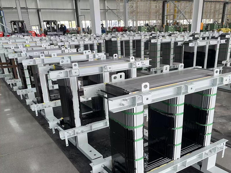
The dry-type transformer is an epoxy resin cast power transformer, unique in that its iron core and windings are not immersed in insulating oil. Its cooling methods mainly include natural air cooling (AN) and forced air cooling (AF). From iron core production to resin casting and assembly, the entire process is self-made by TSTY.Our dry transformer capacity range from 50-3000KVA,voltage from 6.6kv-35kv.

 Product Advantage

Advanced winding technology
High voltage coil: Orthogonal self-flow casting process is adopted to ensure insulation performance and structural stability. Low voltage coil: Self-flow casting process with upper and lower ends sealed to improve sealing and mechanical strength.

Precision casting technology
Transparent resin casting: Breaking through the traditional grey/black resin, using insulating transparent resin, the process and materials are clear at a glance, and the quality is more intuitive.

Core material
Adopting brand-new cold-pressed oriented silicon steel sheet, it has high magnetic permeability and low loss.
Process Optimization
Seven-step 45° fully beveled seams improve aesthetics and electromagnetic performance.

Patented bending clamp design
Replaces traditional channel steel parts, simplifies structure, facilitates installation, and further enhances product quality.
Product Parameters Table
|
SCB10 11KV Dry-type Transformer |
||||||||
|
Rated Capacity |
Voltage Combination |
Vector Group |
No-Load Loss(w) |
Load Loss |
No-Load Current (%) |
Short Circuit Impedance (%) |
||
|
High Voltage(kV) |
Tapping Range |
Low Voltage (kV) |
||||||
|
30 |
11 10.5 10 6.3 6 |
±5% ±2×2.5% |
0.4 |
Dyn 11 or Yyn0 |
190 |
710 |
2.4 |
4 |
|
50 |
270 |
1000 |
2.4 |
|||||
|
80 |
370 |
1380 |
1.8 |
|||||
|
100 |
400 |
1570 |
1.8 |
|||||
|
125 |
470 |
1850 |
1.6 |
|||||
|
160 |
550 |
2130 |
1.6 |
|||||
|
200 |
630 |
2530 |
1.4 |
|||||
|
250 |
720 |
2760 |
1.4 |
|||||
|
315 |
880 |
3470 |
1.2 |
|||||
|
400 |
980 |
3990 |
1.2 |
|||||
|
500 |
1160 |
4880 |
1.2 |
|||||
|
630 |
1350 |
5880 |
1 |
|||||
|
630 |
1300 |
5960 |
1 |
6 |
||||
|
800 |
1520 |
6960 |
1 |
|||||
|
1000 |
1770 |
8130 |
1 |
|||||
|
1250 |
2090 |
9690 |
1 |
|||||
|
1600 |
2450 |
11730 |
1 |
|||||
|
2000 |
3050 |
14450 |
0.8 |
|||||
|
2500 |
3600 |
17170 |
0.8 |
|||||
|
1600 |
2450 |
12900 |
1 |
8 |
||||
|
2000 |
2050 |
15890 |
0.8 |
|||||
|
2500 |
3600 |
18890 |
0.8 |
|||||
|
S20 Dry-type Three-phase Double-winding No-load Voltage Regulation Distribution Transformers |
|||||||
|
Rated Capacity KVA |
Voltage Combination |
No-Load Loss |
Load Loss |
||||
|
High Voltage(kV) |
Tapping Range |
Low Voltage (kV) |
B |
F |
H |
||
|
30 |
11 |
±5% |
|
130 |
605 |
640 |
685 |
|
50 |
185 |
845 |
900 |
965 |
|||
|
80 |
250 |
1160 |
1240 |
1330 |
|||
|
100 |
270 |
1330 |
1415 |
1520 |
|||
|
125 |
320 |
1565 |
1665 |
1780 |
|||
|
160 |
365 |
1800 |
1915 |
2050 |
|||
|
200 |
420 |
2135 |
2275 |
2440 |
|||
|
250 |
490 |
2330 |
2485 |
2665 |
|||
|
315 |
600 |
2945 |
3125 |
3355 |
|||
|
400 |
665 |
3375 |
3590 |
3850 |
|||
|
500 |
790 |
4130 |
4390 |
4705 |
|||
|
630 |
910 |
4975 |
5290 |
5660 |
|||
|
630 |
885 |
5050 |
5365 |
5760 |
|||
|
800 |
1035 |
5895 |
6265 |
6715 |
|||
|
1000 |
1205 |
6885 |
7315 |
7885 |
|||
|
1250 |
1420 |
8190 |
8720 |
9335 |
|||
|
1600 |
1665 |
9945 |
10555 |
11320 |
|||
|
2000 |
2075 |
12240 |
13005 |
14005 |
|||
|
2500 |
2450 |
14535 |
15445 |
16605 |
|||
|
S22 Dry-type Three-phase Double-winding No-load Voltage Regulation Distribution Transformers |
|||||||
|
Rated Capacity KVA |
Voltage Combination |
No-Load Loss |
Load Loss |
||||
|
High Voltage(kV) |
Tapping Range |
Low Voltage (kV) |
B |
F |
H |
||
|
30 |
11 |
±5% |
|
105 |
605 |
640 |
685 |
|
50 |
155 |
845 |
900 |
965 |
|||
|
80 |
210 |
1160 |
1240 |
1330 |
|||
|
100 |
230 |
1330 |
1415 |
1520 |
|||
|
125 |
270 |
1565 |
1665 |
1780 |
|||
|
160 |
310 |
1800 |
1915 |
2050 |
|||
|
200 |
360 |
2135 |
2275 |
2440 |
|||
|
250 |
415 |
2330 |
2485 |
2665 |
|||
|
315 |
510 |
2945 |
3125 |
3355 |
|||
|
400 |
570 |
3375 |
3590 |
3850 |
|||
|
500 |
670 |
4130 |
4390 |
4705 |
|||
|
630 |
775 |
4975 |
5290 |
5660 |
|||
|
630 |
750 |
5050 |
5365 |
5760 |
|||
|
800 |
875 |
5895 |
6265 |
6715 |
|||
|
1000 |
1020 |
6885 |
7315 |
7885 |
|||
|
1250 |
1205 |
8190 |
8720 |
9335 |
|||
|
1600 |
1415 |
9945 |
10555 |
11320 |
|||
|
2000 |
1760 |
12240 |
13005 |
14005 |
|||
|
2500 |
2080 |
14535 |
15445 |
16605 |
|||
R&D Advantages
TSTY currently has 600 employees and a technical R&D team of more than 200 people. It has established a science and technology innovation center to focus on material and process innovation and realize independent research and development of transformers; relying on the national CNAS certified laboratory, each product passes more than ten rigorous tests such as lightning strike and insulation no-load loss to ensure stable operation in the whole environment.
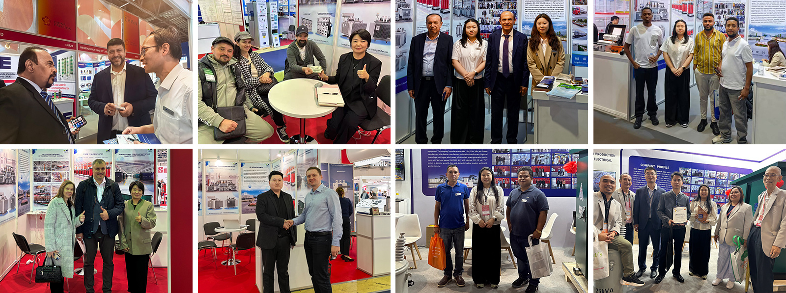
Project Case
TSTY products are exported to more than 80 countries and regions, serving power projects in various regions.
Certificates
All TSTY transformer products have passed CE, IEC, UL,SGS, GOST and other certifications.

 Dry-type Distribution Transformer")
 Dry-type Distribution Transformer")

Qualification
Tel
Industry Cluster District, Jiaxian, Pingdingshan City, Henan Province, China
Oil-immersed Power Transformer
Dry-type Power Transformer
High And Low Voltage Switchgear
Transformer Substation
Supporting Sevice
MESSAGE
Copyright © TSTY Electric Co., Ltd. All Rights Reserved
豫ICP备19019002号 Supported IPV6